
How does it work?
The above diagram shows an FBG located within the core of an optical fiber. If the fiber is injected with a visible spectrum of white light and the FBG has a Bragg wavelength of 540nm (green light), then the spectrum reflected back will center around the Bragg wavelength and allow the remaining visible light spectrum passes through. The reflected spectrum usually is a smooth Gaussian shape.
The Bragg wavelength ( λB ) is defined as
λB = 2neΛ
where 2ne is the effective reflective index of the grating in the fiber, and Λ is the grating period. The grating period is the space between each change in the refractive index.
Important to note that the Bragg wavelength of an FBG can be anything. Fibos uses FBG's that operate within the C-band (1530nm to 1560nm). Our most common FBG is at 1550nm, nominally.
An FBG physically stretches and contracts on the nanometer scale in response to physical changes in the environment which causes the center or Bragg wavelength to change. The grating period, Λ, is the space between each change in the refractive index. The Bragg wavelength is the reference point used to conduct optical measurements. You can see the relationship between the λB and Λ from the equation above. As the period (Λ) changes, the Bragg wavelength changes proportionally. So, how does the grating period change?
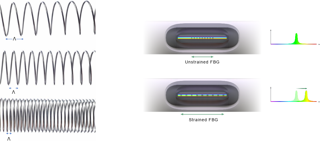
To visualize how the grating period changes, think of the FBG like a miniature spring (below). The grating period is represented by each spiral in the spring. As the spring stretches in tension, the spirals get further and further spaced and the period and overall length increase. The same is true when the spring is compressed. The spirals are more closely spaced and the period and overall length decrease.
As a result of the period changing, the center wavelength changes, moving the reflected spectrum with it:
How external strain impacts the wavelength shift
The center or Bragg wavelength will shift when the fiber is strained. An induced strain can either be compressive or tensile and will result in a change of length of the fiber creating mechanical strain, εm, as seen in equation below:
εm = ΔL/L
As the change in length changes, the strain will change. Strain can either be negative (compressive) or positive (tensile). The relationship between wavelength and strain can be described by the equation below, where the wavelength change represents the shift away from the Bragg wavelength (λB), or initial wavelength (λo):
Δλ = λo * (1- ρԑ) * εm
The change is dependent on two major variables, ρԑ , the photo-elastic coefficient of the fiber and the strain. The photo-elastic coefficient is material dependent. For our purposes, ρԑ = 0.22 for standard optical fiber, and the Bragg wavelength is 1550nm. Therefore, the wavelength shift due to strain is approximately 1.21pm/με (picometers/micro-strain). Again, Figure 3 shows the wavelength shift from the Bragg wavelength when strain is applied.
How temperature impacts the wavelength shift
In addition to being sensitive to strain, an FBG is also temperature sensitive as can be seen in equation.
λ=λo* [ (1-ρe ) *εT + αδ* ∆T]
where αδ is the change of the refractive index and ɛT is the strain induced due to a changing in temperature.
εT = αsp* ∆T
where αsp is expansion coefficient of the material. These two components induce a wavelength shift due to a change in temperature of the glass. As the expansion coefficient of glass is small, the biggest impact to the wavelength shift comes from the change in the refractive index.
At 1550nm, in fused silica telecommunications fiber, the wavelength shift of due to a change in temperature of 1ºC is approximately 10pm. The wavelength shift due to temperature is not linear and does change depending on the absolute temperature of the sensor.
FBG Wavelength Shift Summary
An FBG is sensitive to both strain and temperature, as can be seen in the equation below.
λ=λo* [ (1-ρe ) *ε + αδ* ∆T]
ε = εm + εT
Temperature probes are designed so that the fiber does not experience mechanical strain. To temperature compensate for a strain measurement, it is recommended to use a second FBG that is strain isolated or mounted in a different geometry. This will allow for compensation through a math channel in the data acquisition system.
Multiple FBGs
The Bragg wavelength of an FBG is defined by the pitch of the bragg grating and reflects only that wavelength. Recall it is a wavelength selectable mirror. This means that multiple FBGs can be inscribed on a single optical fiber, allowing multiple sensors to be on a single optical fiber as can be seen below. As long as the wavelengths are inscribed at different nominal bragg wavelengths, the reflected signals will not be impacted by each other.
Next: Learn how an FBG is manufactured here.
 © FIBOS. All rights reserved.